How to Read a Crystal Oscillator Datasheet
You want a crystal oscillator circuit, right? There are a lot of circuits diagram you practise. How much frequency and waveform do y'all want?
This is a uncomplicated Crystal oscillator excursion using 74LS04. It provides a square wave of 1MHz to 10MHz. Using an inverter gate IC and controls output frequencies with crystal.
I will show you 5 circuits ideas beneath.
1# Crystal Oscillator circuit using 74LS04
The oscillators or frequency generators provide a waveform out in various forms.
For case, sine wave, Triangular waveform, and foursquare wave. They generate the frequencies to be a base time. To control an electronic excursion.
The crystal oscillator circuit like this get popular uses in digitals.
The other oscillators will use transistors or FET to connect together with a network circuit. They may use several parts. For example:
- The resistor and a capacitor in the RC oscillator circuit.
- The wires or coil and capacitors are the LC-oscillator circuit
- Using crystal to joint with the resistor.
How Crystal Oscillator circuit Works
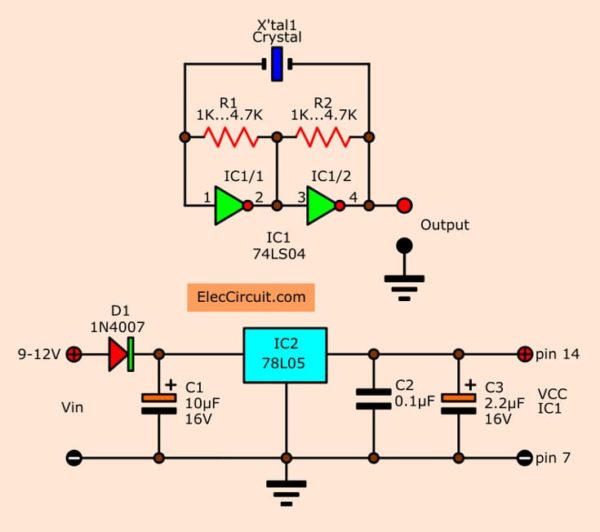
In the excursion below is the simple oscillator that generates the square wave or DC pulse.
They match the crystal and two resistors. To working instead of the RC network circuit. Then, Await at this excursion.
- Use the crystal of 1MHz to 10MHz.
- And the resistors from 1K to four.7K. Both resistors R1 and R2 must be the same resistance.
- Working with two inverter gate inside IC1
They can generate the output constant frequency of 1MHz to ten MHz. It depends on that crystal.
Though the stability of this output frequency has slight defects. Because of its temperature changes while working. Which affects the chapters within the crystal and making frequency tolerances.
But it has very less value. When compared with the common oscillators. That uses RC or LC network.
Next, await at a power supply. This circuit uses a low current consumption and constant power supply of 5V.
Using DCV supply of 9-12 volts comes to DC regulator IC2-78L05. To go on output to A steady voltage. At that place are capacitor C1 and C3 filter current to polish.
Related: 7805 voltage regulator IC: Pinout, Datasheet and instance circuits
And then, C2 pulls a high frequency that contagion from power supply to ground. And protect Interference that may occur to the circuit.
For IC1 may be LS, HC or HCT types.
How to build
You can make easily this circuit on the universal PCB as Figure.
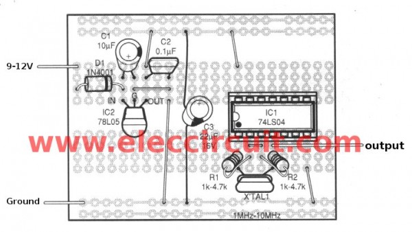
The components layout of this circuit
The components listing
Resistors ¼W +five%
R1, R2_1K to 4.7K
Capacitors
C1: 10uF_16V, Electrolytic
C2: 0.1uF_50V, Polyester
C3: 2.2uF_16V, Electrolytic
Semiconductor
D1: 1N4001, 1A 50V Diode
IC1: 74LS04, Inverter gate IC
IC2: 78L05, 5V regulator IC
Others
XTAL1: Crystal between 1MHz to 10MHz
Universal PCB board
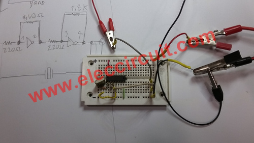
Testing Crystal oscillator using TTL 74LS04
I like the TTL crystal oscillator circuit. Because it is good and enjoyable. It just the signal status "i" and "0" simply. And the frequency generator is a circuit that I like.
However, when studying the TTL IC., Which is the footing of a digital circuit that everyone should learn it.
Although it can be tricky about the power supply to 5V fixed and high current consumption. It tin can be used with very high frequency.
When we demand a highly authentic, it uses the crystal frequency control ameliorate.
This is a simple and inexpensive crystal oscillator circuit, that nosotros use a few parts comprises a TTL digital number SN7404 or SN74LS04 (Parcel contains six inverters), four resistors and a crystal.
The tree inverters gate are biased into their linear regions by R1 to R4, and the crystal provides the feedback.
Oscillation can just occur at the crystals bones frequency, for example, we need frequency is 2MHz, nosotros chose crystals as a two MHZ.
The output signal has formed is Square wave Oscillator at 5Volt p-p.
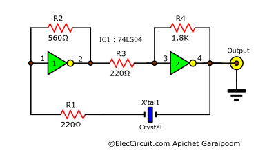
ii# Simple TTL Crystal Oscillator circuit
We exam them on a breadboard. We use a 3.579545 MHz crystal then measure frequency output testify on LED brandish highly accurate.
Even so, If you call back that this circuit is not good enough for you.
You can see the crystal oscillator circuit is as follows:
Quartz picket crystal oscillator circuit
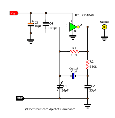
My Friend wants a Pulse Generator Oscillator excursion. Information technology is stable frequency at 32.768KHz with a scout crystal. To his digital CMOS binary counter. So he tell to me even depression prices.
I remember perhaps used the watch crystal and IC4069 or IC4049 inverter CMOS IC.
They are very cheap and we can wait at the general electronics stores.
Read next: 1 MHz fourth dimension base of operations using ceramic filter 10.7Mhz
In the excursion figure outset, be produces to square waveform the other part I think you lot can know them, information technology very unproblematic. If you have upward the voltage ability supply to 12V doing the output volt peak up to 12V as well.
Merely this circuit do not well for high frequency, yous should use this a better: Crystal oscillator using TTL
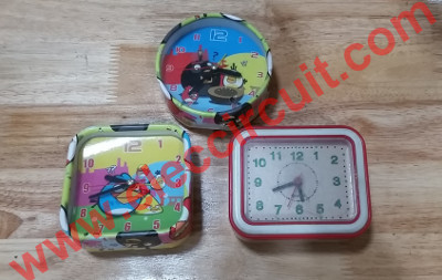
My son gets a watch crystal from the Inexpensive Quartz Alarm Clocks.
They are not yet durable. But we can take a well-used component to reuse new our projects.
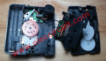
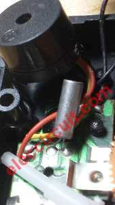
Within Inexpensive Quartz Alarm Clock, there is a component on PCB.

Hither is the lookout man crystal at 32.768KHz
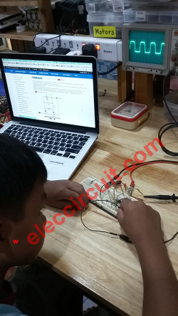
He examined test waveform with oscilloscope. It is a foursquare moving ridge signal.
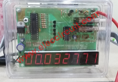
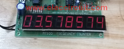
Then mensurate the frequency output by a frequency counter Kits. Information technology is the cheapest tool.
The frequency is 32771Hz or 32.771KHz. Meter accuracy Low. And nosotros tin can adjust the frequency output with the C1-56pF trimmer.
Read also: The 60Hz calibration frequency standards for digital clock using MM5369
iii# CD4060 crystal oscillator circuit
This is a 1Hz oscillator circuit for a standard digital clock, frequency size 1 Hz or 2 Hz. It can exist used in the normal clock circuit. It consists of IC-4060 and IC-4013, the IC-4060 single-interim Oscillator and Counter. of the frequency adamant by the resistor and external capacitor.
In the circuit, IC 4060 is a standard frequency generator with quartz crystal. The adjustment period with C2, and counter circuits within the IC 4060 will exist but 2 Hz frequency dividing out the pivot 3. The IC-4015 is the style of TF / F to dissever two of the Clock indicate frequency is out 1 Hz.
4# Transistor Crystal Oscillator
Next circuit, when yous want to build a ramping waveform using the crystal. And so besides we hands used a single transistor 2N3904 or BC548 that is NPN types.
Read next: Transistor Crystal Oscillator (low volts)
The total voltage the same power supply level. And you alter to some other waveform easily.
Or, You lot can meet Oscillator astable multi-vibrator with the Crystal controller. Below
Check out these related manufactures, too:
- Transistor Crystal Oscillator circuit ideas
- Crystal tester circuit with PCB
- Based time crystal clock generator circuit
Related Posts
Get UPDATE VIA EMAIL
I e'er try to make Electronics Learning Easy .
Source: https://www.eleccircuit.com/simple-crystal-oscillator-circuit/
0 Response to "How to Read a Crystal Oscillator Datasheet"
Post a Comment